Resistance tests are frequently used in motorcycle electrical system troubleshooting. Unlike DC Voltage tests, resistance tests are never performed on a powered circuit. The meter itself provides a small test voltage to the circuit under test.
Introductory Example
One useful resistance test is to measure the load placed on the battery
when the ignition switch is set to the off position. Ideally there should be no
load at all so the battery will not be discharged, even at a very slow rate.
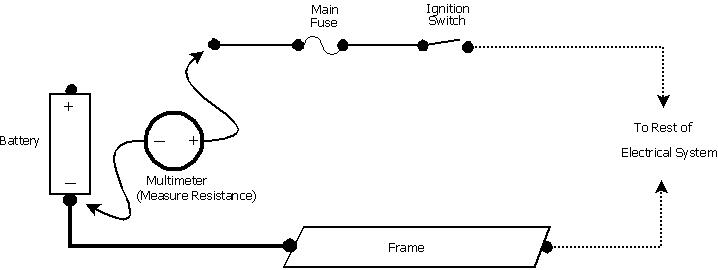
The following test setup shows how this measurement can be performed.

The positive battery cable is disconnected from the battery and the positive multimeter lead is connected to the cable. The multimeter is set to measure Resistance and the negative meter lead is connect to the negative battery terminal. The meter will indicate the load resistance that would normally be seen by the battery.
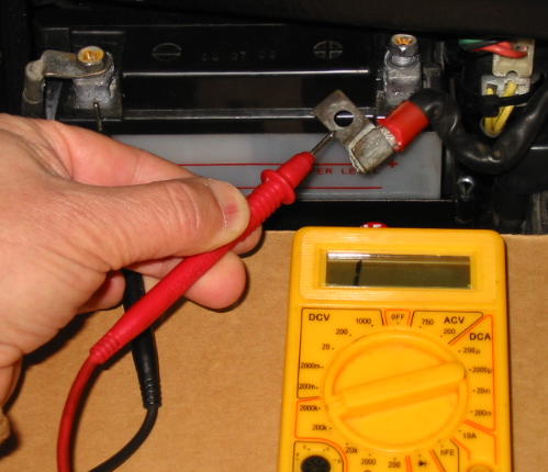
This measurement is being performed here:

The ignition key is set to the off position. The multimeter is set to measure resistance and the maximum resistance range is selected (2000K on this meter). With this range setting, the meter will measure resistance values in the range of zero Ohms to 2,000,000 Ohms. The meter display shows a 1 followed by blanks, meaning the resistance is greater than 2,000,000 Ohms.
The actual load resistance that the battery would see is unkown because it is greater than what the meter is capable of measuring. But we do know it is greater than 2,000,000 Ohms so there is no need to worry about the battery being drained.
If a much lower resistance was observed, the meter could be left connected while attempting to track down the problem. Assuming the electrical system is unmodified and is accurately represented by the wiring diagram, the ignition switch may have faulted by not presenting a completely open circuit when switched off. One quick check would be to unplug the ignition switch and see if the load resistance went up to an extremely high value.
Troubleshooting Short Circuits
One very common problem is a short circuit to ground someplace in the electrical system. This could be due to a wire pinched against the frame, a defective component, or even a previous owner's wiring kluge. It sure would be nice if the multimeter resistance measuring capability could be used to track down the problem as opposed to a brute force alternative such as unplugging things in sequence and looking to see if the fuse blew again this time.
Here the multimeter is connected as described above, but this time the
ignition switch is set to the on position.

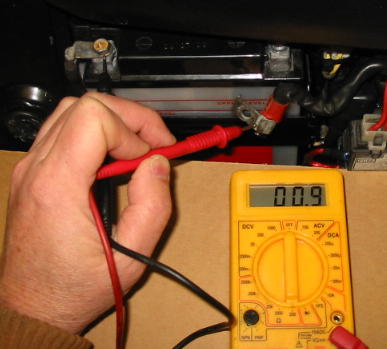
The meter range switch was set to the lowest possible setting, 200 Ohms. The meter reads only 0.9 Ohms, and from our earlier tests we know that much of that is due to the meter leads themselves.
No, there is not a short - this bike has no electrical problems. Small resistance values are commonplace in low voltage electrical systems and are principally due to lights and wire coils (solenoids, motors, and the like). The problem here is that cheap multimeters (and even some more expensive ones) are not well suited for measuring low resistance values.
One way to proceed is to remove or unplug all the low resistance loads normally present in the system. On the CX and GL bikes, this would be all the lights that are normally energized. With all the "good" low resistance loads removed, if the multimeter still reads low it would be due to a short. Then things could be unplugged, wires jiggled, etc. until the low resistance short hopefully disappears.
This method was recently used to diagnose a rear brake light switch that had
shorted out to the frame (not the one in this photo, though).

Although this approach may be adequate for most folks, the professionals usually have more capable (and expensive) tools at their disposal. One such item is the KD Hand Tools 2524 Short Circuit Detector. A Short Sniffer makes quick work of isolating short circuits and is actually fun to use (check out the movies on their web site).
Obviously, resistance tests have widespread application far beyond the introductory examples shown here.
Multimeter Usage
Main Fuse and Grounding
Charging Problems
Ignition Problems
DC Voltage Testing
Resistance Tests
Wiring Fabrication and Repairs
Stray Topics